With ever-increasing computational power, engineers can solve larger FE models in less time. However, optimization is still a serious concern because it is an iterative process and the FE analysis usually needs to be performed multiple times.
Typically, the parts that engineers choose to optimize are only a subset of large assemblies. For example, when optimizing the chassis, the engines and other components attached to it are not designed at the same time. It is not necessary to model all the details of those components not participating in the optimization. Modeling those static components with super-elements is a good time-saving strategy. With super-elements, the behavior of various components is captured with fewer degrees of freedom (master nodes and stiffness/mass matrices) without losing accuracy. It also allows reusing of unchanged and repetitive components in large assemblies and maintains design detail confidentiality between companies/organizations. Other parts that do need to be optimized may actually be repeated in the assembly, either as identical parts or mirror images, and can be represented as clones in the optimization.
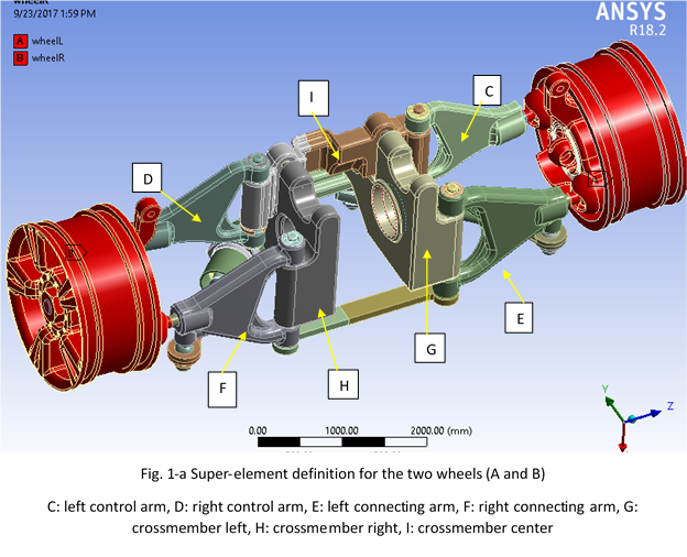
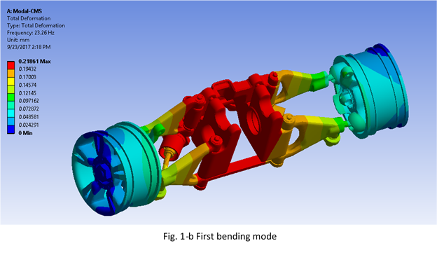
In this topology optimization example, you can see a suspension assembly where the wheels are reduced to super-elements (Fig. 1-a). The Super-elements can be created by regular Substructuring commands or by ANSYS Component Mode Synthesis (CMS) extension. The mode shape for the first bending mode is shown in Fig. 1-b.
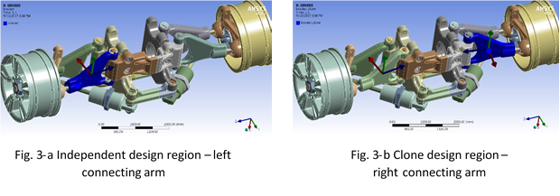
 In this example, we would like to optimize the connecting arms, control arms and cross members. Of course, we want each pair of control arms, connecting arms, and cross-members to use the same topology. Therefore, we will define one component of each pair as independent design region, and the other component as clone region. Cloning is a control that ensures the resulting topology of the clone region to be the same as its corresponding independent parent region. On the independent region, we can apply all the necessary fabrication constraints (casting, extrusion, etc.) that the design requires.
For crossmember left, we define it as independent design region with casting fabrication constraints along the local z direction (Fig. 2-a). The crossmember right is defined as a clone region of the crossmember left (Fig. 2-b).

Similarly, for left connecting arm and left control arm, we define them as independent design regions with extrusion fabrication constraints along the local x direction (Fig. 3-a, 4-a). Correspondingly, we define right connecting arm and right control arm to be clone regions (Fig. 3-b, 4-b).
For the center crossmember, we define extrusion fabrication constraints along the x direction (Fig. 5).
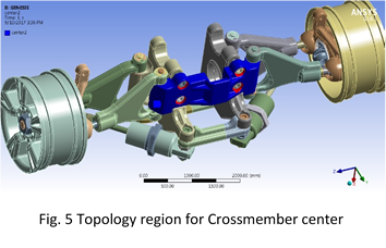
For the optimization problem, we would like to maximize the natural frequency for first bending mode, and maintain the lowest natural frequency value be greater than 24 Hz. We would also like to reduce the mass to less than 40% of the original.
The topology result is shown as below (Fig. 6). The topology design gives clear load path and indicates where the material should be distributed. With cloning fabrication constraints, each pair of corresponding components are enforced to have the same topology.
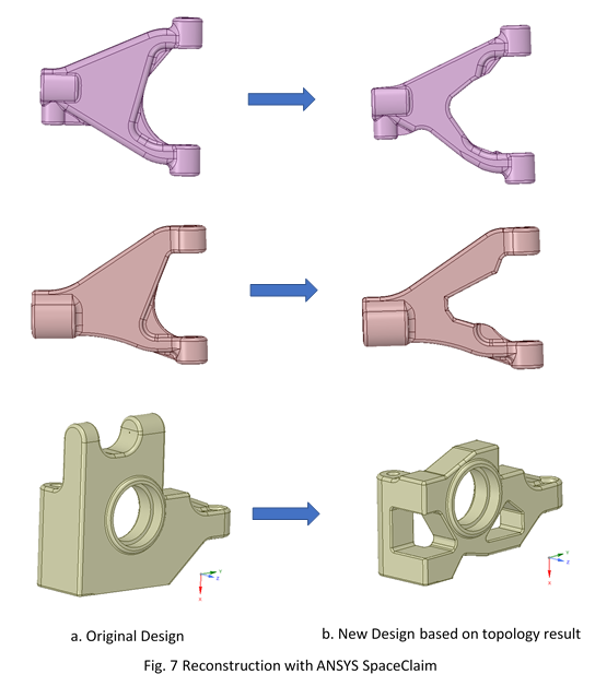
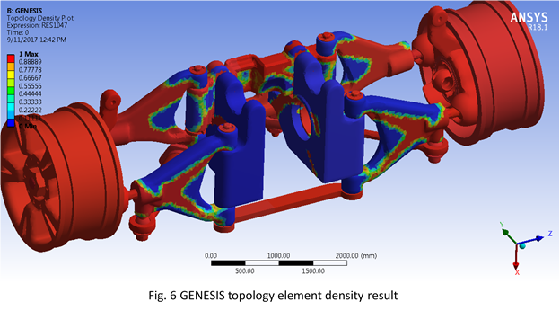 Fig. 7 shows the reconstruction of topology result with ANSYS SpaceClaim. The analysis result on the new design is shown in Fig. 8.
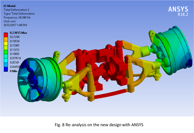 This topology design could be used as the basis for further detailed design. By reducing the two un-designed wheels to super-elements, we were able to save about 1/3 of the computation time. The time savings would be even more significant for larger assemblies with even more components reduced to super-elements.
